Ошибка форд p0320 – Chrysler PT Cruiser ᴰᵉᵉᵖ ᶜʳᵃᶰᵇᵉʳʳʸ › Бортжурнал › Ошибки P0340, P1391 и P0320. Датчики распредвала (CMP) и коленвала (CKP).
Ошибка P0320 пути решения | Ford Trucks Club
В общем не нашел профильную темук по ошибке,а так же какую либо информацию вообще по ней на форуме.Ввлезла ошибка на ходу при попытке разогнаться быстро. После чего машина как будто затроила и пыталась вообще заглохнуть. Позже машина стала глохнуть даже на холостых временами.
Что уже сделано:
1. Менял все свечи и катушки (остались с прошлой замены 100% рабочие — на них глюков не было)
2. Заменил датчики Коленвала и распредвала (именно на них ошибка вроде ругается)
3. Заменил бензонасос в баке.
Сейчас машина на холостых уже не глохнет но при попытке нажать педаль газа двигатель захлебывается и если не отпустить педаль стреляет в глушитель.
Нашел письмо ФОРД в интернете на английском. Там говориться о том что такая ошибка имеет место быть на навиках\экспах определенного времени выпуска по трем причинам:
1. пропуски зажигания
2. Датчики коленвала и распредвала
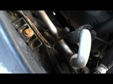
3. Провод идущий с генератора перетирается в месте перегиба через трубку кондиционера (находится в районе правой части аккумулятора снаружи круглая фишка от нее нужно проверять в сторону генератра) — провод перетирается и контакты + — замыкают. — его тоже проверил все ок. Следы замыкания на трубке кондера есть а провод новый — видмо до меня поменяли уже.
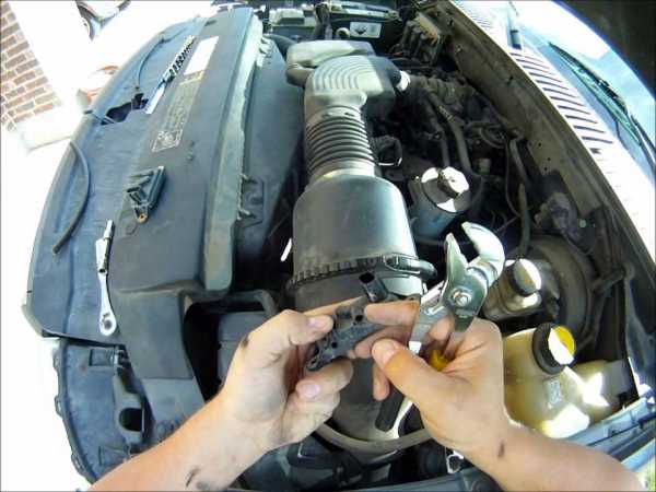
Вчера наткнулся на видео на ютубе Американский мастер говорит что такие проблемы бывают изза датчика положения дросселя и IAC Valve (клапан холостого хода). Как проверить их вроде нашел попробую протестировать щас.
Может кто сталкивался с проблемой помогите найти решение задалбался уже )))
клапан холостого хода при подаче напряжения щелкает но внутр него шток двигается на 1 мм всего. дырку не перекрывает. стоит ли его промывать или только замена??
Добавлено через 3 минуты
и что еще интересно машина на холодную валит просто как новая. как прогреется начинаются приколы.
ford-trucks.club
Hyundai Santa Fe › Бортжурнал › Ошибка P0320 датчик ошибки зажигания. Упал тахометр

В общем случилось у меня такое чудо- начала прыгать стрелка тахометра и загорелся ЧЕК, но при этом двигатель работал ровно.
Не долго думая, подключил сканер OBD (vgate) и программой Torque отсканировал ошибки,
выдал P0320. Покурив форумы, пришел к выводу, что надо менять датчик (27370-38000)
Поискав в интернете нашел его в Exist ценой от 1400 и выше, но как-то туда неудобно заезжать, нашел в евроавто за 1800р.
Купил, поставил, ЧЕК горит. и снова помог мне ТОРК, который удалил ошибку из ЭБУ и все дела.
Тахометр работает. джекичан не горит)))
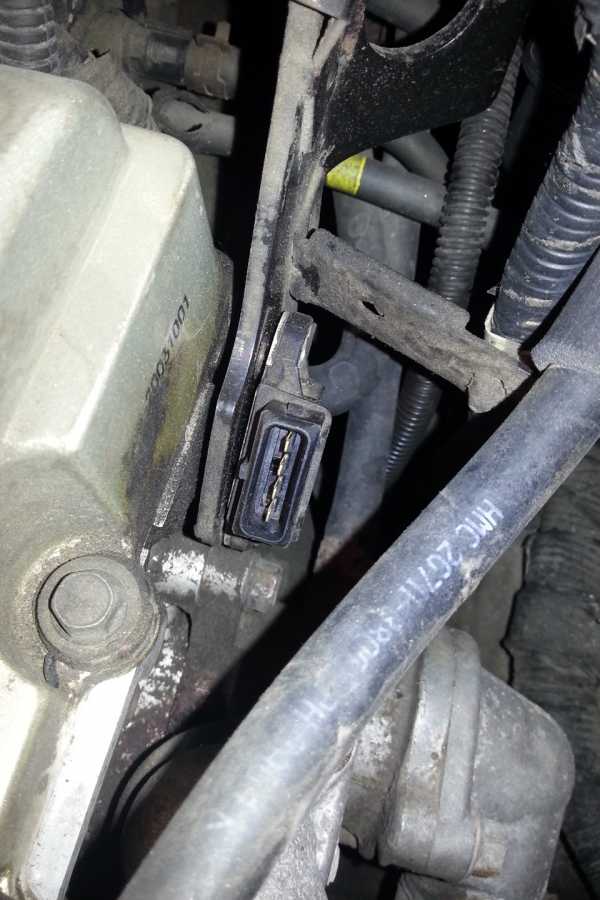
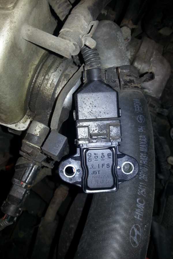
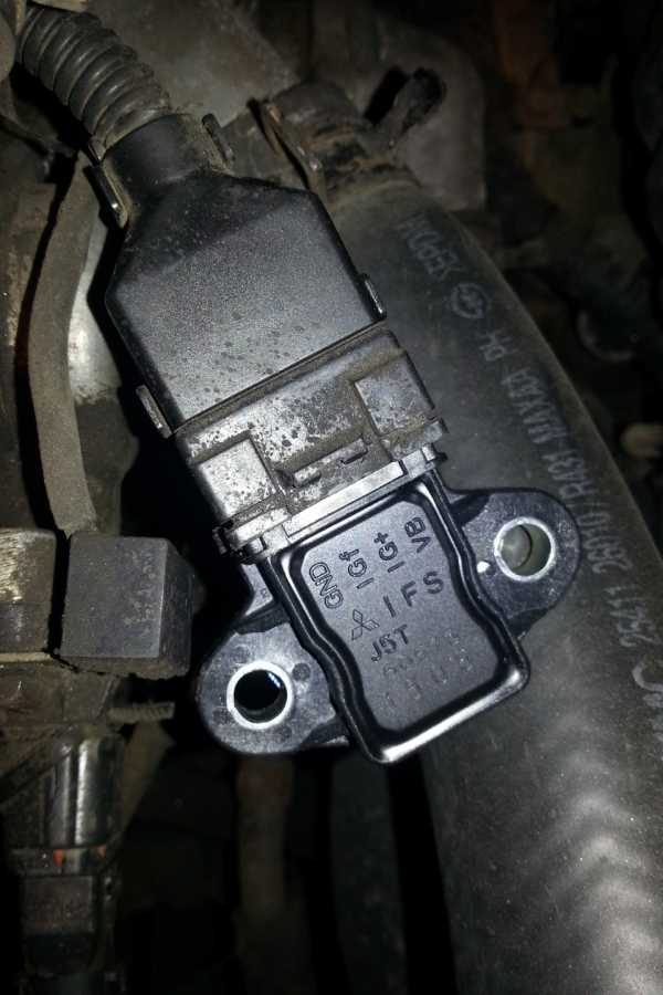
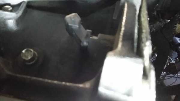
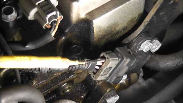
Фото датчика и место его расположения прилагается.
P.S. посмотрев фото-понял, что не очень понятно где он. Справа на двигателе, будет удобнее менять если снять пластиковую крышку с мотора.
Цена вопроса: 1 800 ₽
Нравится 12 Поделиться: Подписаться на машину
www.drive2.ru
Ошибка P0320 Неисправность в цепи распределителя зажигания Форд Ф150 1997
Ошибка P0320 — Ignition/Distributor Engine Speed Input Circuit Malfunction
Уровень важности замены: 3/3
Уровень сложности замены: 3/3Возможные причины
Русский перевод:
Оригинальный (англ):
— Faulty Ignition/Distributor engine speed sensor
— Faulty Crankshaft Position sensor
— Ignition/Distributor engine speed sensor harness is open or shorted
— Ignition/Distributor engine speed sensor circuit poor electrical connection
— Low battery charge
— Faulty Engine Control Module (ECM)
При обнаружении ошибки?
Русский перевод:
Оригинальный (англ):
The P0320 code is triggered when the Engine Control Module (ECM) detects that there is no current at the ignition coil group
Возможные симптомы
Русский перевод:
Оригинальный (англ):
— Engine Light ON (or Service Engine Soon Warning Light)
— Lack/Loss of Power
— The engine may be harder to start
— The engine may stumble or stall
Описание ошибки № P0320
Русский перевод:
Оригинальный (англ):
Ignition failure sensor is used to check whether the spark ignition is occurred correctly or not and also used to tachometer drive. The sensor monitors the voltage difference between a resistance which is on the battery circuit for ignition coil. When the ignition coil works properly, the electric current through the resistance is detected as voltage drop. This is confirmed for every ignition event with the crankshaft sensor and the camshaft sensor. If Engine Control Module (ECM) detects a malfunction, no ignition is possible, so the engine would not start. If there is no ignition signal for a predetermined cycle for one or two ignition coils, an ignition coil circuit failure exists.
Нужна помощь?
Комментарии
Всего просмотров этой страницы: 1296. Сегодня: 3
obdcode.ru
P0320 ошибка ford escape 2.0. Блог, объявления, фотографии
Содержание статьи:Фото Видео Похожие статьи
Ford Mondeo III. Ошибка P 0320. 04 мая Ошибка P 0320 -датчик частоты вращения в распределителе зажигания не исправен! Кто сталкивался и как ее лечить?
Любопытно! За всю свою историю логотип компании изменялся 8 раз, при этом само название Ford никогда не исчезало с эмблемы.Раздел Expedition 2 | Navigator 2 на форуме Ford -Trucks-Club форум тема: Ошибка P 0320 пути решения. Ошибка P 0320 пути решения. Тема от alsinick, создана в.
Ford Escape 2.5 квадратик › Бортжурнал › Болячки Ford Escape 2.5. 7. Последняя проблема, с которой столкнулся на днях. Загорелся check engine, диагностика показала ошибку EVAP PURGE VALVE CIRCUIT SHORT Клапан продувки.

Сайт может работать некорректно. Как проверить их вроде нашел попробую протестировать щас. The suggestion was made to add it to your forum signature some day. Не могла ли растянуться цепь и перепрыгнуть через зубья? Фильтры, температурный датчик, датчик температуры входящего воздуха проверяли?
Разъем напротив левой ноги, под торпедой. Шум остался,но не ярко выраженный. Заменил катушку и поехала! You may not edit your posts. Через нее минус идет на эммитеры ключиков катушки. У меня тоже щелкает, пока ничего не делал. Посмотрите в режиме чтения данных количество ошибок зажигания от холодного до горячего состояния. Глохнет на ходу при сбросе газа, оборотов? Грузовые автомобили и спецтехника. Похоже, тоже известная болячка. По инструкции на забугорном сайте при перегреве ДИОДа появляются именно такие симптомы как у меня.
После этого начинает стрелять в коллектор и чихать..
How to test a Ford crank sensor (Ford 2 0L Case Study)avtodomgroup.ru
Тема: Ошибка p0320 ford mondeo

Видео посмотрело: 2539714
Категория: Европейские автомобили
Описание:Добрый день читатель, ремонт авто своими руками — это собрание всевозможных инструкций (статьи, видео, фотоотчёты, вопросы/ответы) которые наглядно показывают как сделать ремонт своими руками. Для удобства использования сайта etlib.ru все материалы разделены по маркам и моделям авто, а также на категории и типы материалов. При покупке машины автолюбители все чаще интересуются про ремонт автомобиля своими руками. И так все по порядку, длина кузова вашего автомобиля — 3340, ширина — 1261, высота — 1587 мм. Колесная база составляет 2977 мм. Дорожный просвет 156 мм. Автомобиль оснащается гибридным силовым агрегатом. четырех—цилиндровый двигатель оборудован системой обеспечивающей выходную мощность мотора. На каждый двигатель приходится по восемь клапанов. Диаметр одного цилиндра составляет 92 мм, ход поршня – 43 мм. Коленвал двигателя разгоняется до 7000 оборотов в минуту. Максимальный крутящий момент удерживается вплоть до 9000 оборотов в минуту.
Оригинальное название видео:
Дата выхода: 25. 09. 2013 года
Продолжительность: 10:37
Качество: LDRip
Выложил админ: по просьбе Антона
Отзыв автовладельца по имени Тутмос: При не выдающихся габаритах автомобиль безумно вместителен. Огромный багажник (при наличии полноценной запаски), три задних сиденья складываются или снимаются по желанию. Под полом в салоне четыре вещевых ящика, и если передние малы — поместятся например женские туфли, не более, то задние вмещают немало всяческих вещей. Так же имеются 4 ящика под сидениями — не большие, но удобные.Динамика не выдающаяся, трогается машина немного вальяжно, но на крейсерской скорости едет легко, мощности в целом хватает. Ha трассе разгонялся до 140-150 км, больше не рискнул — дорого. По городу так же не чувствуешь себя черепахой.Управляемость хорошая. Быстрых поворотов машина не любит, но проблем они не создают — система стабилизации работает.K основным органа управления и сиденьям претензий нет. Сначала кресло водителя казалось не очень удобным, но сейчас привык. Руль двигается в двух плоскостях. Диапазон салазок кресел велик (мой рост 187 см, люблю сидеть вольготно).Сзади ни дети, ни жена местом тоже не обижены.Климат работает адекватно, в криз-контроль я влюбился (раньше не было), музыка играет не плохо (не меломан), USB вход расположен удобно. Между передними сиденьями вместительный удобный бокс c двумя отделениями.B целом машина и снаружи и внутри выглядит аккуратно и приятно.Настройки подвески тоже стоит занести в «плюс» — идет Сценик плавно и аккуратно. Сравнивать c предыдущими Сузуки ГВ и Маздой 3 даже нет резона. Земля и небо.Что касается шумоизоляци…. первое время после пересадки c Гранд Витары, двигатель Циника не слышал вообще (без шуток). Тем более что не обкатке не газовал, аккуратно ездил. B общем — лишние звуки не донимают.Иногда сильно гудят шины — как зимние, так и летние, родные. Ha других авто такого не было. C чем связано не знаю, думаю, все-таки машина здесь не причем.
Смех в теме: Ходит легенда, что грязные носки, найденные спустя какое-то время, уже чистые.
Необходимые инструменты для работы:1. Молоток;
2. Рожковый ключ на 24; 3. Торцевой ключ 30;
4. нождачка; 5. Плоская отвертка; 6. акб;
Видео инструкция: ошибка p0320 ford mondeo
Форд Мондео 4.Устраняем ошибку Р 0420.Ford mondeo4.
Температурный датчик Ford Mondeo
ddvip.ru
Коды ошибок OBD II Часть 2 P0234 — P0602 — бортжурнал Ford Escape Hybrid 2009 года на DRIVE2
P0234 — Supercharger Overboost Condition The PCM disables (bypasses) the supercharger boost and sets a diagnostic trouble code (DTC) to keep from damaging the powertrain (engine or transmission) during potential harmful operating conditions. Brake torque (brake on and throttle at wide open)
Engine over temperature
Ignition misfire exceeds calibrated threshold
Knock sensor (KS) failure or knock detected
Low speed fuel pump relay not switching
Check for other diagnostic trouble codes accompanying the P0234 or check appropriate and available PIDs related to above possible causes.
P0243 — Supercharger (Boost) Bypass Solenoid Circuit Malfunction The PCM monitors the supercharger (boost) bypass (SCB) solenoid circuit for an electrical failure. The test fails when the signal moves outside the minimum or maximum allowable calibrated parameters for a specified SCB solenoid duty cycle (100% or 0%) by PCM command. VPWR circuit open to SCB solenoid
Damaged SCB solenoid
SCB solenoid circuit open
SCB solenoid circuit shorted to VPWR
Damaged PCM
Disconnect SCB solenoid. Connect test lamp to SCB solenoid harness connector. Cycle SCB driver in PCM by Output Test Mode. Test lamp cycle on and off — SCB solenoid is suspect. Test lamp always on — SCB signal short in harness or PCM. Test always off — SCB signal or VPWR open in harness or PCM.
P0298 — Engine Oil Over Temperature Condition Indicates the Engine Oil Temperature Protection strategy in the PCM has been activated. This will temporarily prohibit high engine speed operation by disabling injectors, therefore reducing the risk of engine damage from high engine oil temperature. Note: On engines which are equipped with an oil temperature sensor, the PCM reads oil temperature to determine if it is excessive. When an oil temperature sensor is not present, the PCM uses an oil algorithm to infer actual temperature. Engine shutdown strategy function is the same on vehicles with and without oil temperature sensors. Very high engine rpm for extended period of time.
Malfunction EOT sensor or circuit (vehicles w/EOT sensor).
Base engine concerns.
Engine operating in high rpm range, due to improper gear selection. May cause Lack/Loss of Power or Surge customer concern.
P0300 — Random Misfire The random misfire DTC indicates multiple cylinders are misfiring or the PCM cannot identify which cylinder is misfiring. Camshaft position sensor (CMP)
Low fuel: less than 1/8 tank
Stuck open EGR valve
Blocked EGR passages
One or more EGR passages may be blocked or partially blocked. If this is the case the Misfire Detection Monitor will indicate the EGR port to check for possible blockage.
P0301 through P0310 — Misfire Detection Monitor The misfire detection monitor is designed to monitor engine misfire and identify the specific cylinder in which the misfire has occurred. Misfire is defined as lack of combustion in a cylinder due to absence of spark, poor fuel metering, poor compression, or any other cause. Ignition system
Fuel injectors
Running out of fuel
EVAP canister purge valve
Fuel pressure
Evaporative emission system
Base engine
The MIL will blink once per second when a misfire is detected severe enough to cause catalyst damage. If the MIL is on steady state, due to a misfire, this will indicate the threshold for emissions was exceeded and cause the vehicle to fail an inspection and maintenance tailpipe test.
P0320 — Ignition Engine Speed Input Circuit Malfunction The ignition engine speed sensor input signal to PCM is continuously monitored. The test fails when the signal indicates that two successive erratic profile ignition pickup (PIP) pulses have occurred. Loose wires/connectors.
Arcing secondary ignition components (coil, wires and plugs)
On board transmitter (2-way radio)
The DTC indicates that two successive erratic PIP pulses occurred.
P0325 — Knock Sensor 1 Circuit Malfunction (Bank 1) See DTC P0326
P0326 — Knock Sensor 1 Circuit Range/ Performance (Bank 1) The knock sensor detects vibrations upon increase and decrease in engine rpm. The knock sensor generates a voltage based on this vibration. Should this voltage go outside a calibrated level a DTC will set. Knock sensor circuit short to GND
Knock sensor circuit short to PWR
Knock sensor circuit open
Damaged knock sensor
Damaged PCM
A knock sensor voltage greater than 0.5V with the key ON and engine OFF indicates a hard fault.
P0330 — Knock Sensor 2 Circuit Malfunction (Bank 2) See DTC P0331
P0331 — Knock Sensor 2 Circuit Range/performance (Bank 2) The knock sensor detects vibration upon increase and decrease in engine rpm. The knock sensor generates a voltage based on this vibration. Should this voltage go outside a calibrated level a DTC will set. Knock sensor circuit short to GND
Knock sensor circuit short to PWR
Damaged knock sensor
Damaged PCM
Knock sensor circuit open
A knock sensor voltage greater than 0.5V with the key ON and engine OFF indicates a hard fault.
P0340 — Camshaft Position (CMP) Sensor Circuit Malfunction The test fails when the PCM can no longer detect the signal from the CMP sensor. CMP circuit open
CMP circuit short to GND
CMP circuit short to PWR
SIG RTN open (VR sensor)
CMP GND open (Hall effect sensor)
CMP misinstalled (Hall effect sensor)
Damaged CMP sensor shielding
Damaged CMP sensor
Damaged PCM
Harness routing, harness alterations, improper shielding, or electrical interference from other improperly functioning systems may have intermittent impact on the CMP signal.
P0350 — Ignition Coil (Undetermined) Primary/ Secondary Circuit Malfunction Each ignition primary circuit is continuously monitored. The test fails when the PCM does not receive a valid IDM pulse signal from the ignition module (integrated in PCM). Open or short in Ignition START/RUN circuit
Open coil driver circuit
Coil driver circuit shorted to ground
Damaged coil
Damaged PCM
Coil driver circuit shorted to VPWR
P0351 Through P0360 — Ignition Coil A through J Primary/ Secondary Circuit Malfunction Each ignition primary circuit is continuously monitored. The test fails when the PCM does not receive a valid IDM pulse signal from the ignition module (integrated in PCM). Open or short in Ignition START/RUN circuit
Open coil driver circuit in harness
Coil driver circuit shorted to ground
Damaged coil
Damaged PCM
Coil driver circuit shorted to PWR
P0400 EGR Flow Failure (outside the minimum or maximum limits) The EEGR system is monitored once per drive cycle during steady state conditions above 48 mph . The test will fail when a malfunction is detected by PCM calculations indicating the EGR flow is less or greater than expected. EEGR valve stuck open or closed
Connector to EEGR not seated
EEGR motor windings shorted or open circuited
No power to EEGR
Harness open or shorted to power or ground
Vacuum signal to MAP restricted or leaking
MAF sensor signal erroneous
Damaged PCM
Carbon build up in EEGR valve seat area
One or more sensor not responding or out of range
All of the following sensors input data to the PCM for proper operation of the EEGR system: ECT, CPS, IAT, MAF, TP, MAP. Any DTC relating to these sensors must be resolved prior to addressing
P0400 code.
P0401 — EGR Flow Insufficient Detected The EGR system is monitored during steady state driving conditions while the EGR is commanded on. The test fails when the signal from the DPF EGR sensor indicates that EGR flow is less than the desired minimum. Vacuum supply
EGR valve stuck closed
EGR valve leaks vacuum
EGR flow path restricted
EGRVR circuit shorted to PWR
VREF open to D.P.F. EGR sensor
D.P.F. EGR sensor downstream hose off or plugged
EGRVR circuit open to PCM
VPWR open to EGRVR solenoid
D.P.F. EGR sensor hoses both off
D.P.F. EGR sensor hoses reversed
Damaged EGR orifice tube
Damaged EGRVR solenoid
Damaged PCM
Perform KOER self-test and look for DTC P1408 as an indication of a hard fault. If P1408 is not present, look for contamination, restrictions, leaks, and intermittents.
P0402 — EGR Flow Excessive Detected The EGR system is monitored for undesired EGR flow during idle. The EGR monitor looks at the DPF EGR signal at idle and compares it to the stored signal measured during key ON and engine OFF. The test fails when the signal at idle is greater than at key ON engine OFF by a calibrated amount. EGR valve stuck open
Plugged EGR vacuum regulator solenoid vent
Plugged EGR tube
Slow responding D.P.F. EGR sensor
Damaged DPF EGR sensor
Improper vacuum hose connection
Plugged vacuum hoses
EGRVR circuit shorted to ground
Damaged EGR vacuum regulator solenoid
Damaged PCM
A DPFEGR PID reading that is greater at idle than during key ON and engine OFF by 0.5 volt or a rough engine idle, may indicate a hard fault.
P0403 EEGR Electric Motor Windings Or Circuits To The PCM Shorted Or Open The EEGR system is continously monitored to check the 4 EEGR motor coils, circuits, and the PCM for opens, shorts to power and ground. If a malfunction is detected the EEGR system will be disabled and additional monitoring will be suspended for the remainder of the drive until the next drive cycle. EEGR motor windings open
Connector to EEGR not seated
Open circuit in harness from PCM to EEGR
Open circuit in PCM
Short circuit in EEGR motor
Short circuit in harness from PCM to EEGR
Short circuit in PCM
If an intermittent condition is suspected the most effective methoid of wiring fault isolation is to use the wiggle test methoid while measuring for shorts and open circuits.
P0411 — Secondary Air Injection (AIR) system upstream flow See DTC P1411
P0412 — Secondary Air Injection System (AIR) circuit malfunction The PCM attempts to control when air is injected in the exhaust. The DTC indicates a Secondary Air injection system AIR circuit fault. AIR circuit open
AIR bypass solenoid fault
Damaged PCM
AIR circuit short to power
Solid state relay fault
Damaged AIR pump
The AIR circuit is normally held high through the AIR bypass solenoid and SSR when the output driver is off. Therefore, a low AIR circuit indicates a driver is always on and a high circuit indicates an open in the PCM.
P0420 — Catalyst System Efficiency Below Threshold (Bank 1) Indicates Bank 1 catalyst system efficiency is below the acceptable threshold Use of leaded fuel
Damaged HO2S
Malfunctioning ECT
High fuel pressure
Damaged exhaust manifold
Damaged catalytic converter
Oil contamination
Cylinder misfiring
Downstream HO2S wires improperly connected
Damaged exhaust system pipe
Damaged muffler/tailpipe assembly
Retarded spark timing
Compare HO2S upstream and downstream switch rate and amplitude. Under normal closed loop fuel conditions, high efficiency catalysts have oxygen storage which makes the switching frequency of the downstream HO2S very slow and reduces the amplitude of those switches as compared to the upstream HO2S. As catalyst efficiency deteriorates, its ability to store oxygen declines and the downstream HO2S signal begins to switch more rapidly with increase amplitude, approaching the switching rate and amplitude of the upstream HO2S. Once beyond an acceptable limit the DTC is set.
P0430 — Catalyst System Efficiency Below Threshold (Bank 2) Indicates Bank 2 catalyst system efficiency is below the acceptable threshold. Use of leaded fuel
Damaged HO2S
Malfunctioning ECT
High fuel pressure
Damaged exhaust manifold
Damaged catalytic converter
Oil contamination
Cylinder misfiring
Downstream HO2S wires improperly connected
Damaged exhaust system pipe
Damaged muffler/tailpipe assembly
Retarded spark timing
Compare HO2S upstream and downstream switch rate and amplitude. Under normal closed loop fuel conditions, high efficiency catalysts have oxygen storage which makes the switching frequency of the downstream HO2S very slow and reduces the amplitude of those switches as compared to the upstream HO2S. As catalyst efficiency deteriorates, its ability to store oxygen declines and the downstream HO2S signal begins to switch more rapidly with increase amplitude, approaching the switching rate and amplitude of the upstream HO2S. Once beyond an acceptable limit the DTC is set.
P0442 — EVAP Control System Leak Detected (Small Leak) The PCM monitors the complete EVAP control system for presence of a small fuel vapor leak. The system failure occurs when a fuel vapor leak from an opening as small as 1.016 mm (0.04 inch) is detected by the EVAP running loss monitor test. After-market EVAP hardware (such as fuel filler cap) non-conforming to required specifications
Small holes or cuts in fuel vapor hoses/tubes
Canister vent solenoid stays partially open on closed command
Damaged, cross-threaded or loosely installed fuel filler cap
Loose fuel vapor hose/tube connections to EVAP system components
EVAP system component seals leaking (EVAP canister purge valve, fuel tank pressure sensor, canister vent solenoid, fuel vapor control valve tube assembly or fuel vapor vent valve assembly)
P0443 — EVAP Control System Canister Purge Valve Circuit Malfunction The PCM monitors the EVAP canister purge valve circuit for an electrical failure. The test fails when the signal moves outside the minimum or maximum allowable calibrated parameters for a specified purge duty cycle by PCM command. VPWR circuit open
EVAP canister purge valve circuit shorted to GND
Damaged EVAP canister purge valve
EVAP canister purge valve circuit open
EVAP canister purge valve circuit shorted to VPWR
Damaged PCM
Monitor EVAPPDC PID and voltage between EVAP canister valve signal and PWR GND in output test mode with key ON engine OFF (or in key ON engine RUNNING mode). EVAPPDC PID at 0% and voltage less than 1.0 volts (or EVAPPDC PID at 100% and voltage less than 0.5 volts) indicates a hard fault.
P0451 — FTP Sensor Circuit Noisy The fuel tank pressure changes greater than 14 inches of H 2 0 in 0.10 seconds. Intermittent open or short in the FTP sensor or the FTP sensor signal.
Monitor FTP PID and does it change from above 15 inches of H 2 0 to below a minus (-) 15 inches of H 2 0 often in 1.0 minute.
P0452 — FTP Sensor Circuit Low Voltage Detected The PCM monitors the EVAP control system FTP sensor input signal to the PCM. The test fails when the signal average drops below a minimum allowable calibrated parameter. Contamination internal to FTP sensor connector
Damaged PCM
FTP circuit shorted to GND or SIG RTN
Damaged FTP sensor
FTP V PID reading less than 0.22 volt with key ON and engine OFF or during any engine operating mode indicates a hard fault.
P0453 — FTP Sensor Circuit High Voltage Detected The PCM monitors the EVAP control system FTP sensor input signal to the PCM. The test fails when the signal average jumps above a minimum allowable calibrated parameter. FTP circuit open
VREF shorted to VPWR
Damaged PCM
FTP circuit shorted to VREF or VPWR
SIG RTN circuit open
Damaged FTP sensor
FTP V PID reading greater than 4.50 volts with key ON and engine OFF or during any engine operating mode indicates a hard fault.
P0455 — EVAP Control System Leak Detected (No Purge Flow or Large Leak) The PCM monitors the complete EVAP control system for no purge flow, the presence of a large fuel vapor leak or multiple small fuel vapor leaks. The system failure occurs when no purge flow (attributed to fuel vapor blockages or restrictions), a large fuel vapor leak or multiple fuel vapor leaks are detected by the EVAP running loss monitor test with the engine running (but not at idle). After-market EVAP hardware (such as fuel filler cap) non-conforming to required specifications
Disconnected or cracked fuel EVAP canister tube, EVAP canister purge outlet tube or EVAP return tube
EVAP canister purge valve stuck closed
Damaged EVAP canister
Damaged or missing fuel filler cap
Insufficient fuel filler cap installation
Loose fuel vapor hose/tube connections to EVAP system components
Blockages or restrictions in fuel vapor hoses/tubes (items also listed under disconnections or cracks)
Fuel vapor control valve tube assembly or fuel vapor vent valve assembly blocked
Canister vent (CV) solenoid stuck open
Mechanically inoperative fuel tank pressure (FTP) sensor
Check for audible vacuum noise or significant fuel odor in the engine compartment or near the EVAP canister and fuel tank.
P0456 — EVAP Control System Leak Detected (Very Small Leak) The PCM monitors the complete EVAP control system for the presence of a very small fuel vapor leak. The system failure occurs when a fuel vapor leak from an opening as small as 0.508 mm (0.020 inch) is detected by the EVAP running loss monitor test. Very small holes or cuts in fuel vapor hoses/tubes.
Loose fuel vapor hose/tube connections to EVAP system components.
EVAP system component seals leaking (refer to Possible Causes under DTC P0442).
P0457 — EVAP Control System Leak Detected (Fuel Filler Cap Loose/Off) A fuel tank pressure change greater than a minus (-) 7 inches of H 2 0 in 30 seconds has occurred after refueling; or there is excessive purge (fuel vapor) flow greater than 0.06 pounds per minute. Fuel filler cap not installed on refueling (storing continuous memory DTC) and «check Fuel Cap» light may also be illuminated.
Fuel filler cap missing, loose or cross-threaded.
Check for missing fuel filler cap or integrity of the cap. If OK, clear continuous memory DTCs and re-initiate EVAP Emission Running Loss Monitor Drive Cycle.
P0460 — Fuel Level Sensor Circuit Malfunction The PCM monitors the fuel level input (FLI) circuit for electrical failure. The test fails when the signal moves outside the minimum or maximum allowable calibrated parameters for a specified fuel fill percentage in the fuel tank. Empty fuel tank
Fuel pump (FP) module stuck open
Incorrectly installed fuel gauge
Damaged instrument cluster
CASE GND circuit open
FLI shorted to VPWR
Damaged PCM
Overfilled fuel tank
Fuel pump (FP) module stuck closed
Damaged fuel gauge
FLI circuit open
FLI circuit shorted to CASE GND or PWR GND
CSE GND shorted to VPWR
Monitor FLI PID and FLI V PID in key ON engine RUNNING. FLI PID at 25% fill (with non matching fuel gauge) and FLI V PID less than 0.90 volts [for FLI PID at 75% fill (with non matching fuel gauge) and FLI V PID greater than 2.45 volts] indicates a hard fault.
P0500 — Vehicle Speed Sensor (VSS) Malfunction Indicates the powertrain control module (PCM) detected an error in the vehicle speed information. Vehicle speed data is received from either the vehicle speed sensor (VSS), transfer case speed sensor (TCSS), anti-lock brake system (ABS) control module, generic electronic module (GEM), or central timer module (CTM). If the engine rpm is above the torque converter stall speed (automatic transmission) and engine load is high, it can be inferred that the vehicle must be moving. If there is insufficient vehicle speed data input, a malfunction is indicated and a DTC is set. On most vehicle applications the malfunction indicator lamp (MIL) will be triggered when this DTC is set. Open in VSS+/VSS- harness circuit.
Open in TCSS signal or TCSS signal return harness circuit.
Short to GND in VSS harness circuit.
Short to GND in TCSS harness circuit.
Short to PWR in VSS harness circuit.
Short to PWR in TCSS harness circuit.
Open or short in the vehicle speed circuit(s) (VSC) between the PCM and appropriate control module.
Damaged VSS or TCSS.
Damaged wheel speed sensors.
Damaged wheel speed sensor harness circuits.
Damage in module(s) connected to VSC/VSS circuit.
Damage drive mechanism for VSS or TCSS.
Monitor VSS PID while driving vehicle. This DTC is set when the PCM detects a sudden loss of vehicle speed signal over a period of time. If vehicle speed data is lost, check the source of where the vehicle speed input originates from: VSS, TCSS, ABS, GEM or CTM. Note: On some MSOF applications, VSS and TCSS PID can be monitor. However if no TCSS PID is available and VSS PID is zero, TCSS circuitry frequency must be checked for loss of sensor signal. If another vehicle electronic module has generated the P0500 and the vehicle does not receive its vehicle speed input from one of the above mention sources (VSS, TCSS, ABS, GEM or CTM). Check the PCM for Output Shaft Speed Sensor (OSS) DTCs. On OSS applications the PCM uses the OSS to calculated the vehicle speed. If no OSS DTCs are found check for correct PCM configuration. Check PCM configuration for correct tire size and axle ratio.
P0501 — Vehicle Speed Sensor (VSS) Range/ Performance Indicates the powertrain control module (PCM) detected an error in the vehicle speed information. This DTC is set the same way as P0500, however the malfunction indicator lamp (MIL) is not triggered. Refer to possible causes for P0500.
Refer to diagnostic aids for P0500.
P0503 — Vehicle Speed Sensor (VSS) Intermittent Indicates poor or noisy VSS performance. Vehicle speed data is received from either the vehicle speed sensor (VSS), transfer case speed sensor (TCSS), anti-lock brake system (ABS) control module, generic electronic module (GEM), or central timer module (CTM). Noisy VSS/TCSS input signal from Radio Frequency Interference/ Electro-Magnetic Interference (RFI/EMI) external sources such as ignition components or charging circuit.
Damaged VSS or driven gears.
Damaged TCSS.
Damaged wiring harness or connectors.
Malfunction in module(s) or circuit connected to VSS/TCSS circuit.
After market add-on.
Monitor VSS PID while driving vehicle, check for intermittent vehicle speed indication. Verify ignition and charging system are functioning correctly.
P0505 — Idle Air Control System Malfunction The PCM attempts to control engine speed during KOER self-test. The test fails when the desired rpm could not be reached or controlled during the self-test. IAC circuit open
VPWR to IAC solenoid open
IAC circuit shorted to PWR
Air inlet is plugged
Damaged IAC valve
Damaged PCM
The IAC solenoid resistance is from 6 to 13 ohms.
P0552 — Power Steering Pressure (PSP) Sensor Circuit Malfunction The PSP sensor input signal to the PCM is continuously monitored.The test fails when the signal is open or shorted to ground. PSP sensor damaged
SIG RTN circuit open or shorted
VREF circuit open or shorted
PSP sensor signal circuit open or shorted
Damaged PCM
The DTC indicates the PSP sensor circuit is open or shorted to ground.
P0553 — Power Steering Pressure (PSP) Sensor Circuit Malfunction The PSP sensor input signal to PCM is continuously monitored. The test fails when the signal is shorted to power. PSP sensor damaged
SIG RTN circuit shorted to power
VREF circuit shorted to power
PSP sensor signal circuit shorted to power
Damaged PCM
The code indicates the PSP sensor circuit is shorted to power.
P0602 — Control Module Programming Error This Diagnostic Trouble Code (DTC) indicates programming error within Vehicle ID block (VID). VID data corrupted by the scan tool during VID reprogramming
Using the scan tool, reprogram the VID block. If PCM does not allow reprogramming of the VID block, reflashing PCM will be required.
P0603 — Powertrain Control Module KAM Test Error Indicates the PCM has experienced an internal memory fault. However there are external items that can cause this DTC. Reprogramming
Battery terminal corrosion
KAPWR to PCM interrupt/open
Loose battery connection
Damaged PCM
If KAPWR is interrupted to the PCM because of a battery or PCM disconnect, DTC can be generated on the first power-up.
www.drive2.ru